Visual Examples
This page contains links and brief descriptions to quick CC3D demos that show off answers to user requests and questions.
For a more complete list of models and demos see the Models page, which include much more complex models as well as models for nanoHUB.
Track the location of a cell with a tail
Want to keep track of where a cell has been? You can use a user created "field" to track the center of mass (COM) of a cell pretty easily. Or, you could create a plot. Here we show both; Left is the cell field showing 4 cells, center is a scientific plot tracking the COM of each cell, right is the track displayed as a field. In the field display, the value assigned to each tracking pixel is the MCS, so the first location gets colored blue and the most recent red in the heat maps.
![]()
Here is the zip file of the CC3D project.
Don't forget to open a new window in Player and tell that window to display "cell_track" instead of the default "Cell_Field".
Create a set of cells that look like fibers
|
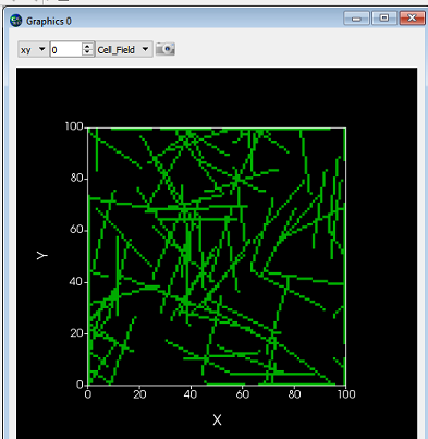
What if you want to generate arbitrary shaped cells in CC3D? Here we'll do the specific case of generating long thin (fibrous) cells. Here is the zip file of the CC3D 2D project and here is the zip file of the CC3D 3D project |
Create a set of cells at defined locations using Python in CC3D
|
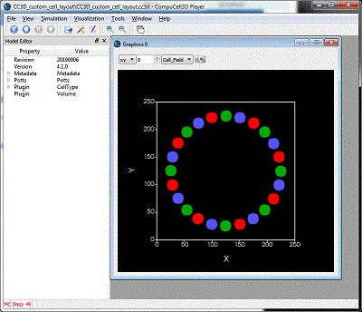
If you can mathematically define your cell locations then CC3D/Python can place your cells. (Or, just use a random number generator if you don't really care exactly where the cells are.) Here we will create a circle of cells of different cell types. Here is the zip file of the CC3D project |
Import an image into CC3D
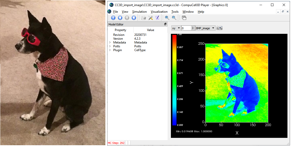
You can use the Python Image Library (PIL or Image) to import an image into CC3D. You can then load a version of the image into a user controlled field. This might be handy for converting a cell layout you created in a program like PowerPoint, or to import an image from a microscope. Or, you never know when you might want to model a dog. ![]()
This process is a bit more complex than the examples above so there is a page describing how to do it.
Below on the left is a bitmap (bmp) photo, on the right the photo after importing into CC3D and displaying it as a user controlled field. We don't have color control in CC3D so the field is displayed with CC3D's standard heat map color bar.
Import an image into CC3D and convert into cells
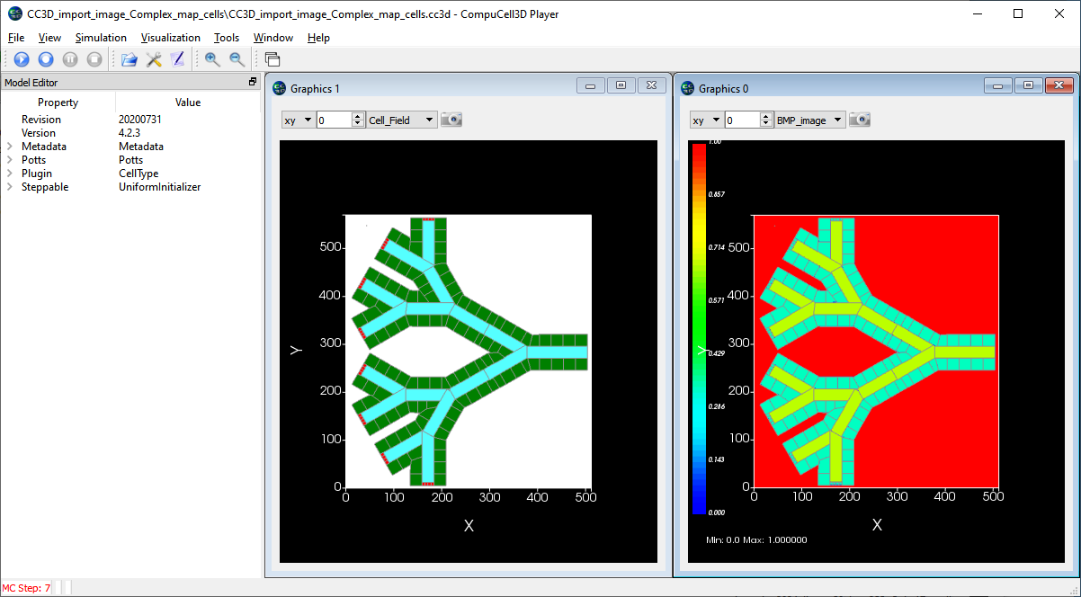
You can use the Python Image Library (PIL, aka Image) to import an image into CC3D and then convert that image into a cell field in CC3D. If you use a drawing program to create cell layouts as colored shapes outlined with black edges, this project will convert the regions into cells based on the colors and use the black lines to define the boundary between cells.
This process is a more complex than the examples above so there is a page describing how to do it.
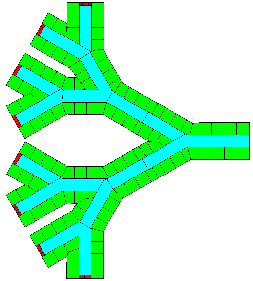
Below on the left is a bitmap (.bmp) image of a cell field created in PowerPoint. The cells are outlined in black and the colors define the cell types. This particular layout is a very crude representation of converging blood vessels in the liver with the green regions representing hepatocytes (the major parenchymal cell of the liver), the blue regions are the blood vessel lumen (that is, the blood) and the small red cells are anchors for creating new blood portions. On the right is a screenshot of CC3D after the image is imported, the right hand images is the image data displayed as a CC3D user-controlled field, the left image is after the image is segmented and the cells are assigned.
 . .
. . 
Simulating a falling cell
|
Simulating a falling object is kind of tricky in CC3D. CC3D's world is very viscous and moving objects tend to stop moving unless a force is applied. A constant force produces a constant velocity where in a non-viscous world a constant force produces an acceleration. Still, it is possible to implement a falling object in CC3D. This is complex enough that we have a page for the CC3D project. |
Animating the results of a CompuCell3D simulation
You have run a simulation and collected a ton of data. How do you show that to someone? How do you represent the dynamic nature of the cells and fields in your CC3D simulation? One useful visualization is to convert screenshots of your simulation into a movie. We have a page with some guidance on how to go about that.
You can also check out our page of simulation movies.
Simple durotaxis model
In durotaxis, cells are guided by changes in stiffness of the extracellular matrix. Here we have a preliminary model in CC3D that implements the basic model described in A Cellular Potts Model of single cell migration in presence of durotaxis. By Allena R, Scianna M, Preziosi L. Math Biosci. 2016 May;275:57-70. doi: 10.1016/j.mbs.2016.02.011. Epub 2016 Mar 9. PMID: 26968932.
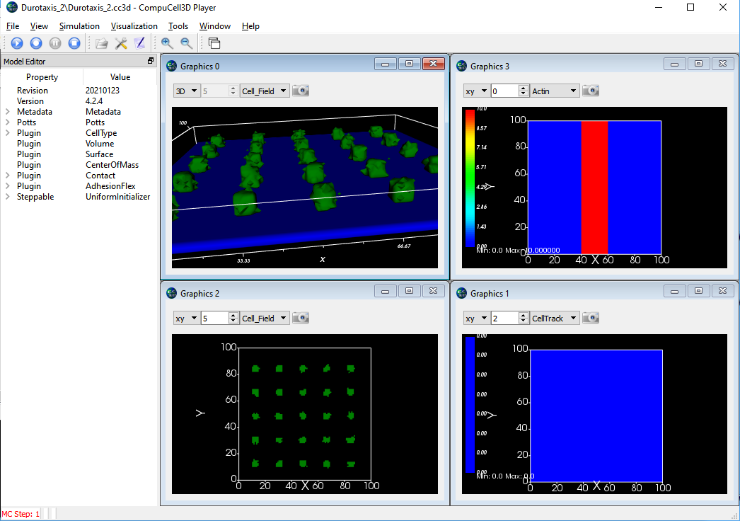
In the screen shots below, the upper left is a 3D view showing a set of green cell (mobile) stuck to a field of fixed blue cells. (Upper right) shows the "actin" amount in the frozen blue cell layer with red being high and blue being low. (Bottom right) The position history for the mobile cells with red being most recent location and blue the oldest locations. (Bottom Left) the 2D cell field just above the fixed layer of cells showing some spreading of the green cells. The CC3D project zip file is here. Note that this model has not been calibrated to the values given in the paper nor has it been extensively tested. It is provided here only as a starting point for further development.
The lower layer (blue) are single voxel cells with per-cell adhesions defined using the AdhesionFlex plugin and with the adhesions defined in the python steppable file. The cells also have regular adhesions defined on a cell type basis. The green cells are slightly sticky to the blue and the green cells strongly resist touching other green cells. In the images below the cell borders are not being drawn so the blue sheet looks like a single cell but it is actually 100^2 individual cells. Note that the green cells have largely migrated to the region of high adhesion by the end of the simulation.
Initial Setup:
After 20,000 MCS:
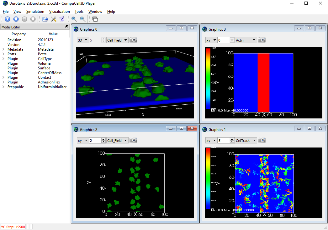
Simple fluid flow model
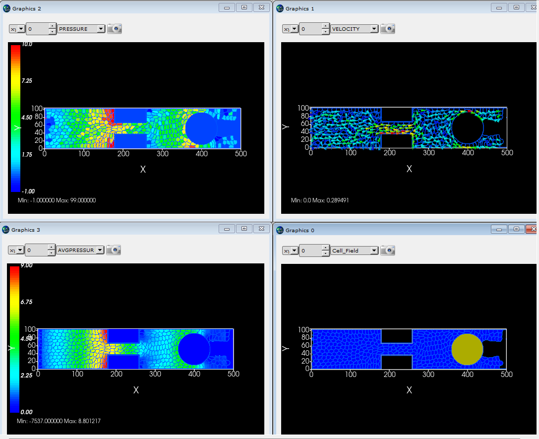
CompuCell3D was not designed to do detailed fluid flow calculations, but it can be used for simple flow cases. Here we model flow through a pipe with a constriction and a round barrier. CompuCell3D "cells" are used to represent portions of fluid. Fluid is created at the left end of the pipe and destroyed at the right end of the pipe. This process creates flow through the pipe from one end to the other. The simulation calculates the velocity of each portion of fluid, its "pressure" (the difference between the target and actual volumes) and also averages the pressure at each pixel in the simulation. |
|
This simulation is based on a CC3D course module developed by Dr. Gilberto Thomas. |
|
Cell movement via lamellipodium
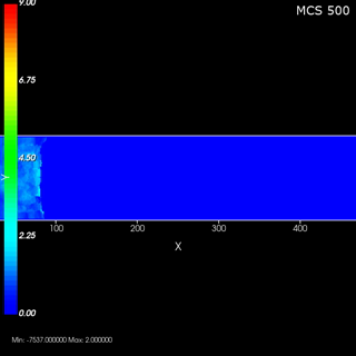
Lamellipodia are flat broad membranous protrusions located at the leading edge of the migrating cells. Lamellipodia determine the cell movement direction by protrusive force that arises from the actin network. For more information on this type of motion see How Cells Crawl. |
|
This simulation is based on a CC3D course module developed by Dr. Gilberto Thomas. |
|
 CompuCell3D